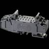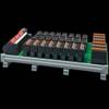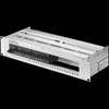
Power-D-Box with pcb-mounted sockets
Model: Brand: Plans - Saltspring Island Chart
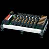
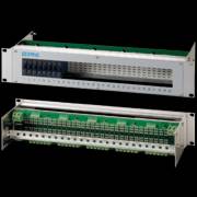
The compact 2U 19inch Power-D-Box with sockets pre-wired on printed circuit board features aluminium profiled cross members with an anoodized front plate. The panel cutout accommodates up to 30 positions numbered 1 through 30. It is possible to have 6, 12, 18, 24 or 30 prepared slots or to have a redundant distribution with up to 2 x 15 positions.
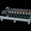
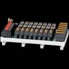
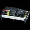
The Power-D-Box accommodates plug-in type circuit breakers 3600/ 3900 and 2210, solid state remote power controller E-1048-700, electronic circuit breaker type ESS20 and electronic circuit protector ESX10. The required device must be specified in the ordering information as both different installation depth and pcb pin assignments must be allowed for.
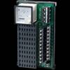
The devices are plugged into corresponding sockets type 63-P10-Si (6 positions each). These sockets are soldered from the rear onto the pcb, holding a certain pre-wiring.
The system is configured with redundancy as standard (2 x 15 positions), but the two groups may be interconnected so as to provide a non-redundant system if required. Line entry within each group is single pole or double pole.
With single pole line entry all slot numbers per group are combined and connected via an M6 terminal stud by means of a ring cable lug.
With double pole line entry, odd and even slot numbers are integrated into one circuit and connected with a 10 mm2 each.
This allows use of double pole circuit breakers.
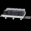
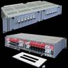
Load outputs are connected by means of screw terminals up to 4 mm2 on the rear of the pcb.
The system offers a number of signalisation possibilities and separation for redundancy is also possible:
- series connection of make contacts (group signalisation via closed circuit current)
- parallel connection of break contacts (double sided for group signalisation via closed circuit current)
- parallel connection of break contacts (only one-sided, second side of break contacts will be connected individually with the terminals for single signalisation via closed or open-circuit current)
Termination is on the rear side by means of screw terminals up to 1.5 mm2 (group connection) and up to 1 mm2 (single signalisation) on the pcb. When using ESS20, ESX10 or E-1048-700, the required Gnd terminals as well as control and reset signals will also be connected via the terminals for group or single signalisation.
Upon request the group distribution (redundancy) can be cancelled by means of jumpers. Additional terminals on the rear side of the rack simplify connection. It is also possible to provide terminals for return lines from the individual loads so as to integrate the necessary external wiring into the rack.
Related Products
-
17plus DIN RAIL MOUNT POWER DISTRIBUTION SYSTEM
-
SVS02 DIN RAIL MOUNT POWER DISTRIBUTION SYSTEM
-
SVS04 DIN RAIL MOUNT POWER DISTRIBUTION SYSTEM
-
SVS09 DIN RAIL MOUNT POWER DISTRIBUTION SYSTEM
-
SVS15 DIN RAIL MOUNT POWER DISTRIBUTION SYSTEM
-
SVS14 DIN RAIL MOUNT POWER DISTRIBUTION SYSTEM
-
SVS16 DIN RAIL MOUNT POWER DISTRIBUTION SYSTEM
-
Power-D-Box with sockets pre-wired
-
SVS20 DIN RAIL MOUNT POWER DISTRIBUTION SYSTEM
-
X1180-R-S00-0542 - 1RU Power Management System
-
PDB-8345-0607-(XX) - 1RU Power Management System
-
X452-S00-0572-4-33X33-(XX) - 2RU Power Management System